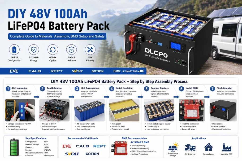
Answer: A 48V 100Ah LiFePO4 battery pack is an industrial-grade stationary energy storage system assembled using a 16S1P architecture. It strings together sixteen 3.2V prismatic cells in series to achieve a 51.2V nominal output, delivering exactly 5.12kWh of stored electrical energy. It serves as the primary technical standard for modern low-voltage home ESS, off-grid solar arrays, telecom backup systems, and high-power mobile marine/RV power networks.
As off-grid solar installations, mobile camper van power setups, and industrial backup grids grow rapidly worldwide, learning how to build a DIY 48V 100Ah battery pack at home has become an essential engineering objective. Sourcing fresh individual cell blocks provides extensive layout customization, simple modular component repairability, and slashes initial hardware acquisition costs by up to 60% compared to prebuilt tier alternatives.
However, lithium system safety requires disciplined engineering validation. Executing rigorous cell inspection, parallel top-balancing, structural mechanical compression, and multi-point short-circuit protection determines whether a stationary asset operates safely or suffers premature performance loss.
1. System Architecture & Technical Parameters Overview
- Multi-Layer Control: Coordinated across an Electrochemical Layer (cells), Control Layer (BMS), and Protection Layer (fuses/enclosure).
- Energy Footprint: Provides 5,120 Watt-hours (5.12kWh) of continuous stationary capacity.
- Voltage Envelope: Operates inside a flat 40.0V discharge floor to a 58.4V charge ceiling.
A stationary 48V-class lithium system is a multi-layer control infrastructure relying on sixteen individual lithium iron phosphate cells wired in series (16S1P). Because each single prismatic block yields a nominal 3.2V potential, the combined series logic provides a flat 51.2V baseline. This uniform voltage configuration integrates natively with international hybrid inverters and stationary solar charge infrastructure.
| Technical Sizing Vector | Verified Factory Baseline Specification |
|---|---|
| Chemistry Configuration | Lithium Iron Phosphate (LiFePO4) / 16S1P Architecture |
| Nominal System Voltage | 51.2VDC (3.2V x 16 Cells in Series) |
| Full Charging Spectrum | 58.4V Peak Target (3.65V per individual cell maximum) |
| Discharge Cutoff Window | 40.0V Absolute Protection Limit (2.50V per individual cell cutoff) |
| Nominal Stored Capacity | 100Ah / 5,120Wh of Usable DC Power Storage |
| System Efficiency Constant | ≥ 95% round-trip conversion efficiency under 0.5C operating rates |
2. Why Do 48V Power Configurations Dominate Modern Solar ESS Architecture?
Answer: Higher operating voltages mathematically reduce line current, allowing for thinner wiring and minimizing thermal losses.
| System Voltage | Current for 5kW Load | Required Cable Size | Relative I²R Heat Loss |
|---|---|---|---|
| 12V Topology | 416.7A | Dual 4/0 AWG | 16x Baseline (Severe Line Loss) |
| 24V Topology | 208.3A | 4/0 AWG | 4x Baseline (Moderate Loss) |
| 48V Topology | 104.2A | 2 AWG / 1/0 AWG | 1x Baseline (Optimal Conduction) |
The choice of battery system voltage alters line current volume, safety profiles, thermal emission parameters, and systemic hardware costs. Shifting from a legacy 12V platform to an industrial 48V architecture slashes line current from 416.7A down to a manageable 104.2A for a 5kW load, shrinking power line heat losses (Power Loss = I²R) by a factor of 16. Managing 416A on a 12V layout forces the integration of massive, cost-prohibitive conductors that generate substantial resistance heating.
By executing a 48V build, system integrators can deploy lighter, highly flexible, and economical 2 AWG or 1/0 AWG copper cabling. Global low-voltage hybrid inverter networks from market leaders like Victron Energy, Deye, Growatt, Solis, and Sungrow optimize their internal DC-DC switching stages around 48V baselines, ensuring peak conversion efficiencies exceeding 97%.
3. Cell Sourcing Engineering Model: Grade A vs. Grade B
Answer: Factory-fresh Grade A cells strictly maintain a capacity deviation under 2% and internal resistance variations below 0.2 mΩ across production batches. Grade B cells exhibit 5% to 15% batch capacity variance, elevated self-discharge rates, and latent internal resistance instability. While Grade B cells are frequently deployed in secondary industrial functions or second-life ESS applications, Grade A cells remain the mandatory standard for high-reliability stationary grids.
Electrochemical cell selection represents the most critical investment in any custom build, representing 70% to 80% of total project expenditure. Sourcing high-quality cells is paramount to ensuring safe operational performance and long-term durability metrics.
- Grade A Cells: Built to full factory specifications. They feature flawless case geometry, fully verified capacity matching, ultra-low internal resistance profiles, and authentic, traceable manufacturer QR codes. For stable energy storage installations, Grade A cells are required.
- Grade B Cells: Down-rated from primary lines due to cell capacity shortfalls or minor structural imperfections. When integrated into a series string, these irregularities compromise system stability and trigger premature cutoff cycles.
To ensure long-term reliability and site safety, source components directly from verified Tier-1 factory networks. Sourcing channels through DLCPO guarantee premium, factory-fresh, and fully traceable solutions from premier global brands including EVE Energy, CALB, REPT Battero, SVOLT, and Gotion High-Tech.
4. Battery Management System (BMS) Control Theory
The BMS functions as a closed-loop control system structured across three distinctive processing vectors:
- Sensing Layer: Continuous real-time data acquisition of cell-level terminal voltages, line currents, and multi-point NTC thermistor temperatures.
- Decision Layer: Compares active telemetry against pre-programmed firmware safety windows to calculate protection thresholds (OVP/UVP/OCP/OTP).
- Actuation Layer: Drives high-current solid-state MOSFET arrays or heavy industrial relays to open or close the primary conduction path instantly upon a fault trigger.
Traditional battery protection devices rely on slow, inefficient passive balancing standards, which dissipate excess energy from higher-voltage cells as heat through small resistors (limited to 30mA–50mA). The JK Smart BMS integrates robust active balancing technology. Instead of wasting energy as heat, JK active balancers employ a dynamic, lossless capacitor or inductor transfer topology to move balancing currents of 0.6A to 2.0A from high-voltage cells to low-voltage cells. This active adjustment maximizes usable block capacity, maintains tight cell consistency under heavy loads, and prolongs total operating life. Advanced JK modules feature built-in Bluetooth for real-time app diagnostics and native CAN bus / RS485 communication interfaces to sync parameters with hybrid inverters. (Explore JK BMS Integration)
5. Mechanical Engineering & Component Checklist
Prepare all necessary high-current components, safety hardware, and technical instruments on a clean, dry, non-conductive workspace before starting assembly:
- 16 × Grade A 100Ah LiFePO4 Cells: Sourced fresh with verified factory internal resistance.
- 1 × 16S JK Smart BMS: Rated at 100A–200A continuous based on inverter surge loads.
- 15 × Solid Pure Copper Busbars: Cross-section rated for continuous maximum ampacity.
- Insulation Materials: High-dielectric fish paper, premium Kapton tape, and FR4 epoxy fiberglass separator plates.
- Layered Safety Overcurrent Protection: High-interrupt Class-T or ANL fuse block, heavy-duty DC isolation breaker, and insulated bulkhead pass-through terminals.
- Specialized Diagnostic Kit: Digital multimeter, AC internal resistance tester (1kHz baseline), calibrated torque wrench, and a hydraulic lug crimper.

6. Step-by-Step Mechanical & Electrical Assembly Flow
Step 1: Cell Inspection, Matching, and Pre-Assembly Sorting
Clean terminal faces, measure the open-circuit voltage (OCV), and test the internal resistance (IR) at a 1kHz baseline. Cells are correctly matched only if the overall voltage deviation sits strictly within 10mV (0.01V) and internal resistance variance remains under 0.2 mΩ. Cells that fall outside these matching thresholds should not be mixed in the same series string, as variations will cause persistent cell drift and uneven charging distribution.
Step 2: Executing a Parallel Top-Balancing Protocol
Top-balancing equalizes the state of charge (SoC) across all 16 cells at their absolute upper voltage limit before they are configured in series. Interconnect all 16 cell blocks in a parallel 1S16P terminal network using copper busbars. Apply a CC/CV benchtop power supply configured with a strict upper cutoff ceiling of 3.65V. Hold saturation voltage until the active current draw tapers down below 0.05C (exactly 5A total for a 100Ah pack). Turn off the supply and let the cells rest for 12 to 24 hours until they settle evenly between 3.40V and 3.45V.
Step 3: Mechanical Alignment, Structural Compression, and Torque
Wrap and place high-grade FR4 epoxy fiberglass or non-conductive electrical fish paper separators between every cell case to mitigate side short-circuit hazards. Arrange the blocks in an alternating configuration to form a robust 16S series alignment. Enclose the pack between rigid end plates, and apply 150 kg to 300 kg of uniform structural mechanical compression force using threaded tie rods to prevent container bulging.
Connect solid copper busbars to the terminals. Using a calibrated digital torque wrench, torque M6 terminal studs to exactly 4–6 Nm, or M8 terminal studs to exactly 9–11 Nm. Insufficient torque builds high contact resistance and hot spots, while excessive torque strips the threads.
Step 4: Installing the 16S Balance Wire Harness Safely
Leave the balance plug isolated from the BMS body during wiring. Secure main B- to Cell 1 Negative. Route Wire 0 to Cell 1 Negative, Wire 1 to Cell 1 Box positive node, and work sequentially up to Wire 16 at Cell 16 Positive. Always use a digital multimeter to measure every pin relative to Pin 0 before plugging the harness in. The voltage must step up uniformly by approximately 3.2V to 3.4V per pin. Once verified, insert the harness into the BMS.
Steps 5-8: Hardware Overcurrent Protection, Parameter Sizing, and Commissioning
Route the primary positive output path through a high-interrupt Class-T safety fuse (rated at 125%-150% of maximum continuous inverter current draw) alongside a double-pole DC isolation breaker. Wake up the JK Smart BMS by holding down the power switch or applying a charge source. Open the Bluetooth application and configure the internal protection fields: OVP at 3.65V, OVP Recovery at 3.55V, UVP at 2.50V, Active Balance Start at 3.40V, and Low Temperature Charge Protection at 0°C to prevent irreversible lithium plating.
7. Failure Mode & Effects Analysis (FMEA) Matrix
Industrial storage development requires mathematical risk modeling to map out systemic root causes, system-level effects, and engineered hardware mitigations under strict boundary constraints.
| FMEA Failure Identifiers | Primary Root Cause | Systemic Effect Profile | Engineered Hardware Mitigation |
|---|---|---|---|
| Cell Imbalance Drift | Latent internal resistance variation or uneven cell aging. | Premature BMS protection triggers, reducing overall usable capacity. | High-current smart active balancing + automated periodic calibration cycles. |
| Busbar Thermal Hotspots | Terminal nut torque inconsistency or contact face oxidation. | Localized heat generation risking adjacent separator melt. | Calibrated digital torque validation + routine infrared thermal imaging scans. |
| BMS MOSFET Welded State | Sustained overcurrent electrical stress or inductive voltage spikes. | Complete loss of software cutoff control over conduction paths. | Upstream secondary mechanical protection via high-interrupt Class-T safety fuses. |
| Deep Cell Reversal Fault | Imbalanced discharge string combined with UVP safety bypass. | Irreversible internal copper dendrite growth causing dead shorts. | Hard-coded, hardware-level non-bypassable UVP cutoff enforcement. |
8. DIY vs. Prebuilt 48V Battery Systems: Is it Worth It in 2026?
Answer: For off-grid solar installations requiring modular scalability and simple repair paths, a DIY assembly using Tier-1 Grade A cells reduces component acquisition expenditures by 30% to 60%. However, commercial prebuilt rack systems are better suited for users requiring zero-labor assembly and a single multi-year product warranty.
| Engineering Metric | The DIY Assembly Path | Prebuilt Server-Rack Alternatives |
|---|---|---|
| Financial Sourcing Outlay | Significantly Lower: Reduces total costs by 30% to 60% compared to retail solutions. | Higher Premium: Reflects manufacturer assembly labor and logistics markup. |
| Granular System Control | Absolute: Every component, parameter, and protection setting can be customized by the builder. | Restricted: Proprietary parameters are typically locked behind encrypted factory firewalls. |
| Long-Term Repairability | High Simplification: Individual aging cells or a faulty BMS can be easily replaced at minimal cost. | Complex: Requires shipping heavy, fully integrated units back to a regional service station. |
| Formal Technical Warranty | None: The builder assumes all operational safety liability and structural risks. | Comprehensive: Backed by a standard 5 to 10-year manufacturer replacement warranty. |
9. Is a DIY LiFePO4 Battery Pack Safe for Home Energy Storage?
Answer: LiFePO4 chemistry is highly stable and does not support self-sustaining thermal runaway under ordinary operating conditions. However, if a primary protection layer fails during a dead short circuit, an instantaneous discharge surge potentially exceeding 1000–2000A depending on pack configuration and internal resistance can manifest. This creates intense arc-flashing and cable ignition hazards. Sourcing a dedicated secondary fault layer (such as a Class-T fuse) is mandatory to clear high-amp spikes instantly.
Operating lithium energy installations requires strict safety steps. Always design with redundant protection. Never bypass programmed BMS voltage cutoffs. Ensure all high-current tools are fully wrapped with non-conductive insulation tape during assembly to prevent cross-busbar short circuits. Place the finished cell stack within a sealed, fire-resistant steel enclosure, and implement a dedicated manual circuit breaker to isolate the bank during emergency maintenance runs.
10. Technical Support FAQ
Q1: What is the realistic service lifespan of a DIY 48V 100Ah LiFePO4 battery pack?
A: When engineered using factory-fresh Tier-1 Grade A cells with matched internal resistance and managed by an advanced smart BMS within conservative voltage limits, a LiFePO4 battery pack provides excellent multi-year stability and performance in stationary energy storage applications.
Q2: What is the precise charging voltage profile for a 16S LiFePO4 battery bank?
A: The ideal target bulk/absorption voltage for a standard 16S configuration is 56.8V to 57.6V (which translates to 3.55V–3.60V per cell). This ensures a full capacity charge while avoiding upper electrochemical voltage stress.
Q3: Is it safe to charge a LiFePO4 battery bank in sub-zero freezing temperatures?
A: Absolutely not. Attempting to charge LiFePO4 cells when internal temperatures fall below 0°C (32°F) causes permanent internal damage due to lithium plating, which risks internal short circuits. Always ensure your BMS low-temperature charge protection is activated or install integrated thermal heating pads.
Q4: Can I connect multiple 48V 100Ah battery packs in parallel for future expansion?
A: Yes. You can scale your system capacity by wiring identical packs in parallel. However, each pack must have its own independent BMS and Class-T safety fuse, and the pack voltages must be tightly matched (within 0.05V) before physical linking via equal-length cables to a common star busbar.
Q5: Why is individual pack fusing required in parallel storage topologies?
A: Independent pack fusing isolates a single failing string in the event of an internal dead short circuit, preventing the other parallel battery banks from dumping thousands of amps into the faulted pack, thereby avoiding catastrophic system failures.
Q6: What is the primary safety risk involved when building a DIY lithium battery pack?
A: White LiFePO4 chemistry is highly stable against thermal runaway, the primary risk in DIY builds is an accidental DC arc flash or short circuit caused by tool contact across exposed busbars. This can instantaneously unleash a severe electrical discharge potentially exceeding 1000–2000A depending on pack configuration and internal resistance, welding metal components and causing severe burns.
Q7: How does cell compression physically protect prismatic battery packs?
A: Moderate, uniform physical compression (typically 150 kg to 300 kg of clamping force) prevents structural delamination of the internal anode/cathode layers during routine expansion and contraction cycles, preserving low internal resistance and maximizing overall structural longevity.
Q8: Is it necessary to establish active communication links between the BMS and the hybrid inverter?
A: It is optional but highly recommended. While open loop voltage-based profiles are acceptable for basic DIY setups, closed loop CAN bus or RS485 communication allows the inverter to receive real-time, cell-level State of Charge (SoC), operational current, and temperature dynamics, maximizing tracking accuracy and protection responsiveness.
Q9: Can a single 48V 100Ah LiFePO4 battery run heavy household air conditioning loads?
A: Yes, provided the paired hybrid inverter is sized correctly to manage the startup surge current. A single 48V 100Ah pack stores 5.12kWh of total energy; running a continuous 1,000W climate control load will deplete the pack in approximately 4 to 4.5 hours under safe Depth of Discharge boundaries.
⚠️ Technical Disclaimer & Quality Commitment
The information and technical analysis published by DLCPO Power Technology Co., Ltd. are provided for general informational and educational purposes only. While we strive to maintain accurate and up-to-date information regarding LiFePO4, LTO, Sodium-ion, and evolving energy storage technologies, technical specifications, industry standards, and product performance data may be updated without prior notice as technologies continue to evolve.
Performance metrics referenced in this content—including cycle life, charging characteristics, thermal stability, operating temperature range, and energy efficiency—serve as general reference values. Actual real-world performance may vary depending on operating conditions, environmental factors, application design, system integration, and Battery Management System (BMS) configuration. The information presented should not be interpreted as a product warranty, contractual commitment, or guaranteed performance specification.
Our Factory-Direct Commitment: As a dedicated manufacturer and authorized battery integration partner, DLCPO supplies 100% brand-new Grade-A battery cells sourced directly from qualified manufacturing facilities. Combined with professional battery pack engineering and customized BMS solutions, our approach helps customers reduce risks associated with long-term inventory storage, inconsistent cell quality, and system integration challenges while supporting optimal cell freshness and traceability.
For project-specific engineering support, official factory datasheets, battery sourcing inquiries, or customized energy storage solutions, please contact our technical team directly at dlcpo@dlcpo.com or visit our official website dlcpo.com.
Intended Audience & Topics: This content is designed for engineers, battery integrators, OEM/ODM manufacturers, procurement professionals, and energy storage developers seeking reliable technical insights regarding DLCPO battery solutions, LiFePO4 batteries, LTO batteries, Sodium-ion batteries, battery pack design, BMS integration, and energy storage systems (ESS).
Technical insights and data provided by DLCPO Solutions Team.
