LiFePO4 battery module electrical connection design often becomes a defining factor in whether a pack stays balanced for a decade — or drifts within months. There is a question that follows almost every battery system integrator into their second or third prototype build: why does the pack keep drifting out of balance, even when the cells test perfectly on the bench? Having spent close to two decades in lithium battery manufacturing — and now working alongside industrial and wholesale clients through DLCPO Power Technology Co., supplying Grade‑A LiFePO₄ and LTO cells from CALB, EVE, REPT, SVOLT, GOTION, and others — we have learned that the answer often lives in the connections.
Not the cells. Not the enclosure. The busbars, the weld joints, the bolted terminals, and the design thinking behind them. In large‑format lithium battery PACK manufacturing, electrical connection architecture quietly determines whether a system delivers stable current for a decade or develops hot spots within its first year of field service. This article explores how connection methods, design requirements, and safety strategies come together to create modules that industrial users and LiFePO₄ battery wholesalers can truly rely on.
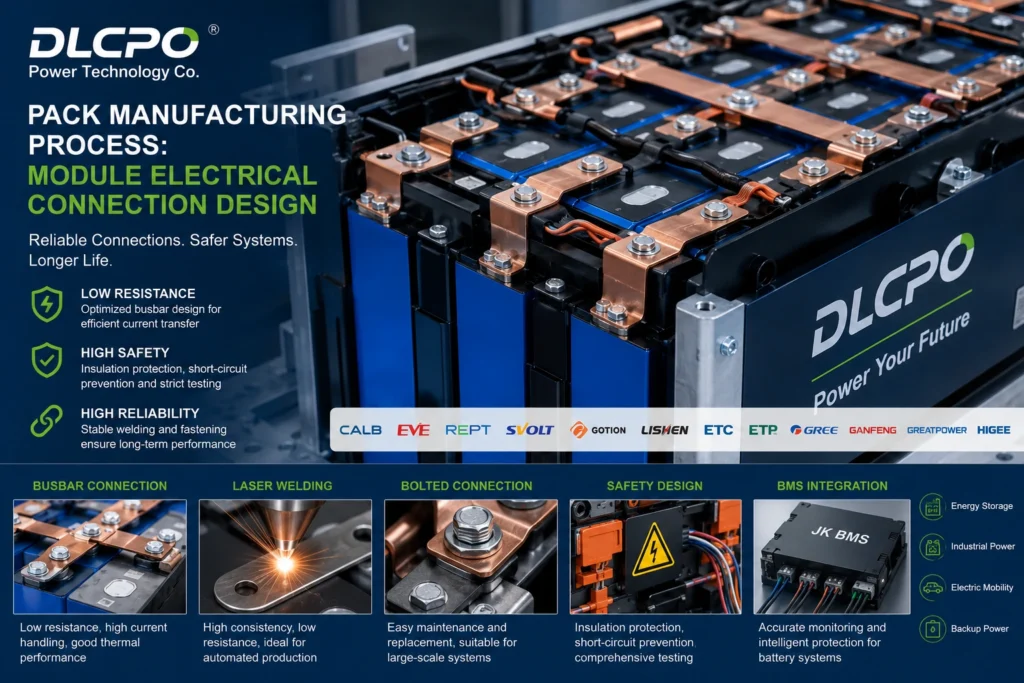
Connection Methods That Define LiFePO4 Battery Module Electrical Design
Battery module electrical connections, broadly speaking, fall into three families: busbar‑based connections (realized through welding or mechanical fastening), bolted screw‑type assemblies, and mechanical crimping. Which route an integrator takes depends less on theory than on production volume, serviceability expectations, and the environment the pack will work in.
Welded busbar connections have become dominant in automated production lines — and for good reason. Laser welding, in particular, creates a metallurgically bonded joint with contact resistance in the micro‑ohm range. When paired with industrial robotics, it delivers exceptional consistency and minimal thermal impact on the cell. Copper busbars offer superior conductivity for high‑current applications; aluminum busbars help reduce weight and cost. The trade‑off is permanence. A welded module is not designed for field repair. If a single cell fails, the entire module usually gets replaced, which is why this approach thrives in high‑volume EV and containerized energy storage production where units are treated as sealed components.
Bolted screw‑type connections take a different philosophy. Threaded terminals on large‑format prismatic cells — the kind commonly found on cells from REPT, Gotion, or LISHEN — allow busbars to be fastened mechanically. This gives integrators something welding cannot: serviceability. In applications like telecom backup systems, marine battery banks, or commercial EV fleets where maintenance access matters, the ability to replace a damaged cell or reconfigure a string without destroying the module is a genuine operational advantage. Assembly torque, however, becomes a critical process parameter. Too loose and contact resistance climbs; too tight and you risk deforming the terminal seal, compromising the cell’s internal integrity over years of thermal cycling. Many advanced production lines now use digital torque traceability to lock in consistency across every joint.
Mechanical crimping, the third path, relies on pressure‑fit connections without heat or fasteners. Its primary advantage is full reversibility — ideal where pack recycling and cell‑level replacement are design requirements — though achieving uniform contact pressure at scale demands sophisticated tooling and precision geometry control.
A practical observation from our work supporting integrators across different markets: the choice between these methods is rarely about which is “better” in absolute terms. It’s about which one aligns with your assembly capabilities, your end customer’s maintenance model, and the certification pathway you are targeting.
When Small Resistances Turn into Big Problems
The real reason connection design matters becomes visible only after months or years of cycling. Inside a battery module, hundreds of amperes flow continuously through conductive components that look deceptively simple. A small increase in contact resistance — maybe from an uneven weld, a slightly loose bolt, or oxidation at an interface — creates localized heating. That heat accelerates degradation in the cell immediately adjacent to it. The BMS registers a voltage deviation, begins balancing more aggressively, and gradually the entire string’s usable capacity erodes.
Field failures in lithium battery systems rarely announce themselves with a single catastrophic event. They begin subtly: uneven current distribution, micro‑cracks in welds, busbar thickness that looked adequate on a datasheet but proves marginal under sustained peak load. Thermal expansion then compounds the problem. Copper busbars, aluminum terminals, steel fasteners, and cell casings all expand and contract at different rates. In an application like a cold‑storage warehouse forklift — cycling between -20°C and ambient temperature multiple times per shift — that differential movement applies mechanical stress to every connection point. A flexible busbar structure or an expansion compensation feature can absorb it; a rigid bolt that was not torqued with thread‑locking measures may gradually loosen.
This is also where voltage consistency and parallel path optimization enter the design conversation. Parallel‑connected cells must see similar resistance paths. Even a small asymmetry in conductor length or interface quality can cause unequal current sharing. Cells that carry a little more current age faster, generate more heat, and pull the entire module out of balance. In several ESS projects we have evaluated alongside our engineering partners, redesigning busbar geometry reduced module temperature deviation by more than 20% during high‑rate discharge testing — a result that translates directly into longer cycle life and fewer field service calls.
Building Safety into Every Connection Point
Safety in a lithium battery module is not a single component’s job. Electrical design, insulation strategy, thermal control, and BMS logic work together as an integrated framework. When we support customers developing packs for industrial energy storage or extreme‑cold LTO applications, the conversation almost always returns to how connections influence this framework.
Insulation protection is the first layer. High‑voltage modules require reliable barriers — PET film, epoxy‑coated separators, heat‑resistant plastic holders, insulating gaskets — between conductive parts and structural components. Designers must account for dust, moisture, and long‑term material aging. In humid or coastal environments where many export‑oriented industrial systems operate, insulation degradation can become a serious reliability challenge if environmental protection standards are not baked into the design from day one.
Short‑circuit prevention is equally fundamental. One overlooked metal fragment inside a module can create catastrophic consequences. Professional PACK manufacturing facilities implement vision inspection, automated polarity verification, insulation resistance testing, and end‑of‑line high‑voltage checks. Connection spacing must comply with creepage and clearance requirements based on the operating voltage — and this is where standards such as IEC 62619 (safety requirements for industrial lithium batteries) and UN 38.3 (transport testing… (transport testing, including vibration, thermal cycling, and shock) draw the boundary lines. A bolted terminal assembly that passes bench testing may fail under the vibration profile of UN 38.3 if the mechanical fastening was not validated for that specific resonance range. A weld that measures beautifully on the production floor can develop micro‑cracks after thermal cycling if material compatibility was not considered.
Then there is the BMS signal layer. Modern systems using JK BMS units — which we supply alongside our cells — require stable voltage sampling and accurate temperature monitoring. Poor sense‑wire routing or electromagnetic interference from high‑current switching can introduce noise that makes the BMS read voltages that do not match reality. A capable BMS with active balancing can only protect the pack if it receives clean input signals. This is why harness routing, shielding strategy, and connector locking mechanisms are not afterthoughts; they are part of the module’s electrical connection design from the start. For integrators working on telecom UPS or off‑grid infrastructure, this signal integrity layer often becomes the deciding factor between a trouble‑free deployment and recurring false alarms.
From Cells to System: The DLCPO Perspective
Our position as a Shenzhen‑based cell distributor and PACK engineering partner gives us a slightly different lens on this topic. Because DLCPO Power Technology operates on a strict “No Stock” policy, every Grade‑A LiFePO₄ and LTO cell we ship is produced to order — never pulled from aging inventory. This zero‑stock strategy means cells arrive with maximum electrochemical activity and consistent batch characteristics. In practical terms, the module’s electrical connections can be designed around predictable cell behavior rather than compensating for chemically degraded or mismatched cells that have been sitting on a shelf.
We also find that providing engineering support beyond cell sourcing makes a measurable difference in project timelines. Whether our clients are assembling battery packs for industrial AGVs and forklifts, containerized storage, or marine propulsion, our team in Shenzhen helps with everything from busbar material recommendations and torque‑sequence specifications to BMS protocol logic and fault diagnostics. Connection design is not a one‑size‑fits‑all exercise, and having access to practical, production‑tested guidance can move a project from prototype to certified product significantly faster.
Where Interconnection Technology Is Heading
Battery module connection technology continues to evolve alongside the growth of large‑scale energy storage and industrial electrification. Several trends are becoming increasingly visible on production floors and in R&D labs: integrated structural busbars that double as mechanical support, CCS (Cell Contact System) architectures that combine sensing and power delivery in a single flexible circuit, automated laser welding with AI‑assisted defect recognition, lightweight composite conductive materials, and smart temperature‑sensing interconnects that feed real‑time thermal data back to the BMS.
As cell energy densities climb and industrial users demand longer warranty periods, the margin for error in connection design keeps shrinking. Selecting stable cell suppliers — brands like CALB, EVE, REPT, SVOLT, GOTION, LISHEN, GANFENG, GREAT POWER, and HIGEE — is one part of the equation. Equally important is understanding how those cells get integrated into a safe, serviceable, and durable PACK structure.
Ready to design battery modules with reliable, high‑performance electrical connections? Contact DLCPO Power Technology today for fresh Grade‑A LiFePO₄ and LTO cells, JK BMS systems, and factory‑direct engineering support from Shenzhen.
FAQ
1. What’s the most common cause of electrical connection failure in LiFePO₄ battery modules?
From our field experience, inconsistent assembly torque in bolted connections and insufficient weld penetration in laser‑welded joints lead the list. Both create localized hot spots that accelerate cell degradation. Using DLCPO’s fresh Grade‑A cells — sourced from manufacturers like EVE, CALB, and REPT — helps because terminal dimensions and surface quality are batch‑consistent, reducing variability.
2. Should I use welded or bolted connections for my industrial LiFePO₄ battery pack?
It depends on your production model and customer needs. Welded connections offer lower long‑term resistance and better automation scalability — ideal for sealed, high‑volume packs. Bolted connections provide field serviceability and are often preferred for telecom, marine, and commercial EV applications. DLCPO supplies both weld‑terminal and screw‑terminal prismatic cells and can advise on which format fits your project.
3. How does busbar design affect overall battery lifespan?
Poorly designed busbars create unequal current paths between parallel cells, leading to uneven aging, hot spots, and SOC drift. Optimizing busbar geometry for balanced resistance and thermal performance can reduce temperature deviation and extend cycle life. This is one of the most impactful — and often overlooked — parts of PACK design.
4. What role does the JK BMS play in connection reliability?
The JK BMS units we provide feature active balancing and real‑time voltage monitoring. If a poor connection causes elevated resistance in a cell group, the BMS detects the resulting voltage deviation and can flag it for maintenance — often before it becomes a safety issue. Clean signal routing and proper harness design are essential for the BMS to do its job accurately.
5. What certifications should I verify when sourcing cells for export‑ready battery packs?
At minimum, confirm that cells carry UN 38.3 certification for transport and IEC 62619 compliance for industrial safety. Traceability — including factory QR codes and test data — is equally important for customs clearance and end‑customer confidence. Every DLCPO shipment includes this documentation as standard.
⚠️ Important Technical Disclaimer
The information provided in this article by DLCPO Power Technology Co., Ltd. is intended for general informational and educational purposes only. While we strive to ensure the accuracy of technical data regarding LiFePO4, LTO, and other battery chemistries, industry standards and product specifications are subject to continuous R&D updates.
Please note that actual battery performance—including cycle life, charging speeds, and thermal stability—is heavily dependent on specific real-world application parameters, environmental conditions, and the proper integration of a Battery Management System (BMS). The data presented does not constitute a binding performance guarantee.
DLCPO assumes no liability for any direct, indirect, or incidental damages arising from the use or misinterpretation of this content. For project-specific engineering advice, official datasheets, and verified Grade-A cell procurement, please contact our technical sales team directly at dlcpo@dlcpo.com.
